Eventually a bunch of J310’s that I ordered arrived. So I proceeded to pull out 10 units at random to match.
I built another tiny little test board to measure IDSS. The circuit is so ridiculously simple that it was hardly worth the effort of building a board. It only grounds the gate to the source. You measure the current flowing into the drain. But it was handy because of the test socket. It made testing a whole group reasonably quick.
I found measuring IDSS this way on a J310 to be a moving target. The current would continue to fall off the longer I let it flow. Internal JFET heating I assume. I got sick of waiting for it to stabilise by about the 30 second mark. So in the end I plugged them in, counted to 10 seconds and then recorded the value shown on the DMM at that time. Not an exacting science but I was only interested in the relative IDSS value between FET’s.
I also matched each of the J310’s to the transistor I had designated unit #1. I found that two transistors with a very similar IDSS would also present very good balance in the bridge. Somewhat predictable I know. But always nice to have something you only suspect as being true proved by experimental method.
In the end I selected two FET’s with not quite the highest value of IDSS because they were better matched in the bridge. This matched pair recorded only 0.002v using the bridge as the picture above shows. Sorry about the quality of these images. They are a bit dark. More lighting practice required.
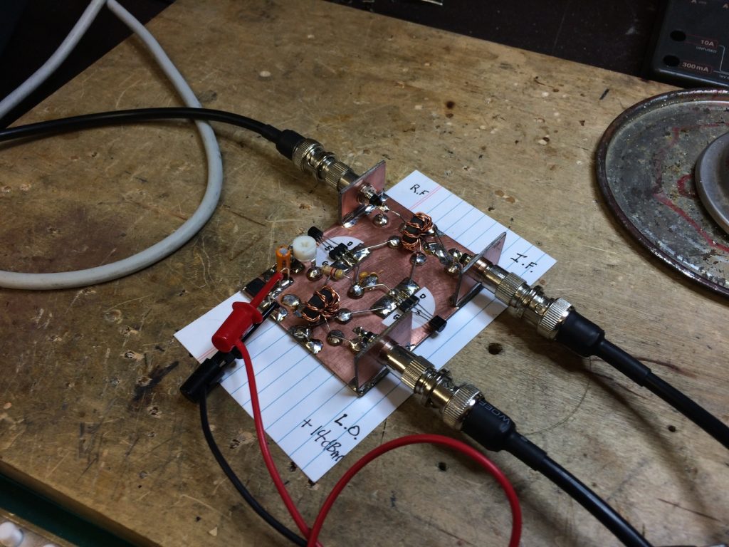
So here is my version of the KISS mixer. Above is the Minima KISS Mixer as per Farhan’s original circuit. I used FT37-50 toroids instead of FT37-43’s because I didn’t have any of the smaller ones on hand. I used thicker wire 0.5mm to match. Apart from that and my unusual choice of RF connector it is built as per the original.
This unit has the adjustable 0-5v DC bias which is why the power leads are connected. On my version of the KISS mixer I found that the bias adjustment seemed to have very little effect on the mixer output levels. It had some, just not a significant amount. LO leakage only varied by about 1dB and the wanted RF product by only 0.5dB over the entire bias range. One of my next experiments is to see if the adjustment range actually increases if your FET’s are poorly matched.
This next picture is a modified version of the KISS mixer. Very early on in the life of the Minima Freelists mailing group Joe W3JDR suggested an alternate bias method. This method does not require the 5 volt bias regulator. It directly grounds both FET sources and connects the centre tap of the LO Gate transformer not directly to ground but instead floats that point by connection to ground via a parallel 200K Ohm resistor and a 0.1uF capacitor. You can read Joe’s original post about it here.
So do they work? Yes, I’m very pleased to say. They both do.
So what did each version perform like?
See for yourself.
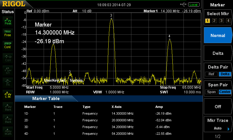
These Spectrum Analyser screen shots were taken with the LO from the actual Si570 at +14dBm and the 20Mhz IF at -10dBm into the mixer. The Rigol DSA-815 is looking at the RF port (simulated TX mode).
Above is the output from the original Minima mixer.
While this last image is the output from the modified mixer.
Next up. The Minima Low Pass Filters and some more mixer testing…
73, Steve. VK2SJA


