Well I had a lot of fun building the Minima 20Mhz crystal filter. There is no shortage of good information on the topic of crystal ladder filter construction scattered around the Internet. So I’ll try not to tediously duplicate but rather focus on what I learnt specific to the Minima. For those starting from point zero here is just one link to a document containing a reasonable summary of the current state-of-the-art:-
Crystal characterization and crystal filter design.
The first thing of import I learnt about the Minima filter is that it is a QER filter. QER being short for “Quasi-Equiripple”. The QER filter topology is easily distinguished by the use of the two parallel crystals at either end of the filter. This filter type is attributed to none other than David Gordon-Smith G3UUR. Who also developed what is most likely the most popular method for measurement of crystal motional parameters, the G3UUR shifted frequency method.
What I found out about QER filters is that they are “relatively new”. So there is not a whole lot of information about them around the Net. They are a variant of the Min-Loss Cohn Filter topology which substantially reduces unwanted passband ripple. Which is a very good thing. Min-Loss Cohn is popular for simple QRP designs because it is simple. As all of the capacitors in the network have the same value. The only thing wrong with the Cohn filter is the rather large ripple in the passband. QER maintains the simplicity but substantially removes the ripple.
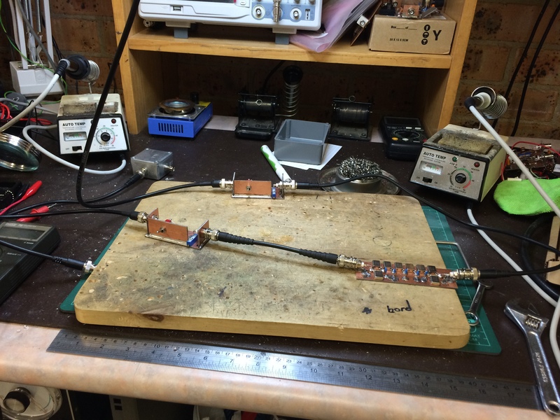
So I decided that I would use the G3UUR shifted frequency method to characterize my crystals. Which seemed appropriate given that the filter was a QER filter. So step one was to build a G3UUR test oscillator and measure two frequencies per crystal for each crystal in my set of 42. Above you can see the test oscillator and frequency meter in action. It is going to be difficult for some to find a counter that will give 1Hz accuracy at 20Mhz. But I’d suggest that the exercise is still worth-while even if you have to scale back to a 10Hz resolution.
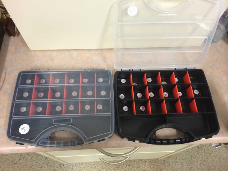
So I sorted and labeled each of my crystals with a number from 1 to 42 and then proceeded to measure them. During the process I found three crystals from this batch that wouldn’t even start in the test oscillator. Not quite sure what would have happened if I had managed to select one of these for inclusion in a filter at random. But I’m thinking only bad things would likely come of it.
What you’re trying to do here is pick a matched set of crystals that oscillate at very nearly the same frequency, or as close as you can get them. The data was all entered into LibreOffice Calc spreadsheet and with a bit of software magic the crystals were all helpfully sorted. Such that picking a group of 8 crystals with the closest possible frequency span could be done at a glance.
If you’re not planning on doing the whole “crystal characterization” filter design thing. Then I’d still recommend that you at least do this step. You could use the Minima BFO as the test oscillator. If nothing else it will remove faulty crystals from the equation and it is much more likely that you will end up with a crystal filter instead of a crystal brick wall.
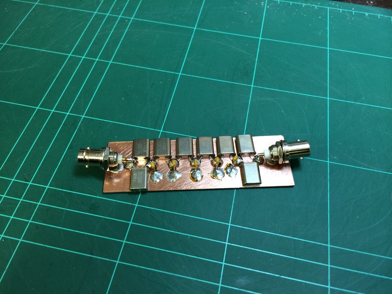
So I went ahead and built the crystal ladder filter that you can see above with my “matched” crystals. Oddly enough I (foolishly?) chose to build this filter arbitrarily with the 100pF capacitors as specified in the Minima circuit diagram. Partly because I wanted to see what the result would be. But mostly because at that time I was still trying to get my head around the software design process.
Obviously if you have gone to all the trouble of properly characterizing your crystals then the objective would be to feed that data into some design Software. Requesting it to give you a particular desired bandwidth for your new filter based upon the motional parameters you have carefully collected. The software should then tell you (predict) the inter-stage capacitor values (all the same value for QER) and the filters characteristic impedance. All hopefully with a high degree of accuracy. So just grabbing five 100pF capacitors and slapping them in like I did is somewhat missing the point entirely.
So the resulting filter was connected up to the Rigol DSA-815 and a plot emerged. I have to say I was pretty pleased to see this picture. But what’s this, the 3dB BW is only 1.9kHz? Others have been reporting 4.5, 6 and even higher 3dB bandwidths! Which just goes to show that the resulting bandwidth is very dependent upon the actual crystals being used and their motional parameters.
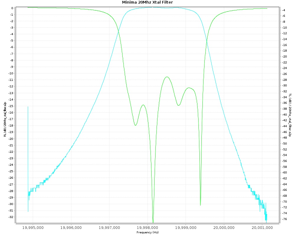
The plot above is the same 1.9kHz filter. It was generated with the vna/J software using a MiniVNA-Pro. This plot shows both the S21 transmission loss plot and the S11 refection or return loss plot overlayed. You can see more detail from this instrument as the minimum bandwidth resolution of the Rigol DSA-815 is only 100Hz. But the Rigol is more than up to the task of providing crystal ladder filter sweeps for Amateur purposes. The return loss plot looks pretty messy and not anything like the ones you see in text books. To be honest I don’t really have a good feel for how good or bad this filters return loss is. Time, more reading and some experimentation will reveal all.
Along the way I had discovered, to the best of my Internet sleuthing, that there is currently only one software design tool which will allow you to predict and model the QER filter. And that software package is called Dishal.
So I fired up Dishal as seen above and proceeded to try to understand the inner workings and why my filter was so narrow compared to those built by others. I’m going to use Dishal to predict the required capacitor values for a filter 3dB bandwidth of 2.7kHz. Given that I tell Dishal what -my- specific crystal motional parameters are.
I should mention that QER filters with all capacitors being of equal value makes experimenting easy. It wouldn’t be hard to arrive at a desired filter bandwidth simply by logical substitution of the capacitors. Reducing the capacitor value(s) increases bandwidth while increasing capacitor value(s) decreases bandwidth. So with some educated guess-work and only a few wholesale capacitor bank change outs. You should arrive pretty close to where you want to be in terms of bandwidth. Of course you’re not going to know what your filter impedance is until you test/measure it. Which is the other very important thing that your filter design software will tell you. But it can all be done. So even if you don’t have any method of sweeping a filter then you can still build them!
The first thing one needs to get your head around with QER and Dishal is that nearly all of the program functionality displayed above, including the ability the plot pretty filter plots. Is not applicable to QER filters. If you’re using this software to design a QER filter, then you are simply going to use two or three program features available from the drop-down menus at the top of the screen. The option “Xtal”, and then later in the design process the “QER (G3UUR)” option. Likely followed by the “LC-Match” to assist in building a matching network.
Under the “Xtal” option you get two sub-options for the two most popular methods for performing Crystal Characterisation of the motional parameters. The G3UUR method and the 3dB BW method. I used the G3UUR method but later cross checked with the 3dB BW method. I found that either produced results so close that it wouldn’t matter which you use. So the selection of method will be something of personal preference. Perhaps dictated by the test equipment you own. If you’re lucky enough to already own a VNA then the 3dB BW method may well be easier.
After some trial and error I discovered that Dishal could be used to accurately predict the capacitors required to build a filter of a given bandwidth. What I found however was that the crystal holder capacitance value was critical. I had to measure the capacitance value between the two crystal leads, record this value. Then I needed to short the two leads together and measure the capacitance between both the shorted leads and the metal case of the actual crystal. The second amount then needed to be deducted from the first and the result is entered into Dishal as the Cp (pF) figure. It was only the difference of a couple of “Puffs” but it made a world of difference to the prediction.
So after carefully collecting the crystal frequencies(s) of all my crystals. Then selecting the 8 crystals closest together in band-spread. Only 65 Hz spread between them. Then measuring the holder capacitance of all these eight crystals. And then averaging all of these eight values to arrive at a single value to enter into Dishal for each parameter. Dishal then proceeded to predict 65pF as being required for a 3dB bandwidth of 2.7kHz with some 94 ohms of in/out impedance. I substituted a standard capacitor value of 68pF and went ahead and built my second filter. I had decided to keep the 1.9kHz 3dB BW filter. After all it was a good looking filter!
And the result?
Again the plot above was produced by vna/J and a MiniVNA-Pro. Using the marker math function of vna/J it was revealed that the 3dB bandwith was:-
19,997.524 Low
20,000.175 High
Actual 3dB bandwidth = 2.651 kHz! Not too bad a result for 2.7kHz requested.
A Dishal help file warns that calculations are based on mathematically perfect components. Which of course don’t exist in the real world. The resulting losses mainly in the capacitors leads to a slightly smaller 3dB bandwidth than that calculated. The suggestion is to work out what your desired 6dB BW would be and then enter that as the requested 3dB BW (i.e. lie to the program essentially). This will apparently place you *very* close to your actual desired BW. The fact that I did not do this would go a long way towards explaining my smaller than requested BW.
So I was very happy with the new filters width. But what’s that wavy pattern across the top of the passband? Ripple! Nearly 3dB of it at a quick glance at the plot. Now I asked the question:- “How much ripple is acceptable?” and basically the answer came back:- “How much are you prepared to put up with?”. I even found a commercial manufacturers technical bulletin talking about adjusting a filter matching network which said that anything “less than 3dB” of ripple was to be deemed acceptable. Admittedly this alignment procedure came from the valve era and I think our standards today are a little higher, even for the home-brewer. Suffice to say that 3dB is probably too much and if you have it down to less than 0.5dB ripple then that is considered very good indeed.
So where did the ripple come from? The ripple from a practical stand point is caused by two things. Failure to match your crystal filters input and output impedance properly and how wide your filter is. The wider the filter, the more ripple it is going to have. This means that building an exotic narrow CW filter is actually pretty easy. A 400Hz CW filter using the traditional Cohn topology is probably not going to have any significant passband ripple. But if you try to build a filter with wider SSB bandwidths, like the 2.7kHz 3dB BW filter above, then keeping the ripple under control gets harder, much harder.
It also goes to show how lucky I was with the first filter I’d built. The bandwidth may have been an unexpectedly narrow 1.9kHz but the combination of narrow BW and what must have been a filter with very, VERY close to 50 ohms input and output impedance resulted in a very flat passband.
What to do to reduce the ripple? I needed to impedance match the input and output of my new 2.7kHz filter to 50 ohms.
Now Dishal had predicted about 94 ohms impedance in/out. So I guess I could have just matched to that. But I had altered the capacitor values slightly. By now I had learnt that sometimes very small values of capacitance make big differences. I guess I could have used Dishal, and altered the requested bandwidth to arrive at the actual value of capacitance I had used and then read off the predicted Zo in/out. But I wasn’t sure if this approach was valid. So in the end I went and built a couple of in-line resistive terminators.
You place these either side of the filter. Then adjust the mutli-turn pots for best passband response while looking at the spectrum analyzer filter sweep in real time. The resistive terminations cause bucket loads of additional insertion loss but you don’t worry about that. This adjustment is subjective and a bit tricky. As I had to keep adjusting the DSA-815 settings to keep the top of the passband visible. Adjusting the resistors tended to make important parts of the trace disappear off the bottom of the analyzer screen. Eventually I arrived at what I thought looked like the flattest passband response. And when the terminators were removed and the actual resistance checked with an Ohm meter I was pretty close to 75 ohms.
So I then asked the Dishal LC-Match to give me the values for a L-Pad to match 75 ohms to 50 ohms. Which gave series inductance of 0.28uH with parallel capacitance of 75pF. I substituted 75pF for a standard value of 82pF and with a bit of help from the AADE LC meter (fantastic tool this!) built some 0.28uH air-core coils and the result looked something like this:-
And the actual filter response now looked like this:-
~ 0.5dB passband ripple!
As Colonel Hannibal from the “A-Team” would say:- “You gotta love it when a plan comes together!”
73, Steve.


Hi Steve:
Really wonderful work! — Anyone contemplating a Minima build should read your blog prior to working on the front-end.
You also have a perfect SSB 20 MHZ IF filter for later?
Best, Todd—-VE7BPO—–
Thanks Todd,
I find building a Minima is a great endeavor. Because it breaks down a SSB radio transceiver into simple digestible blocks. Which in turn creates a logical process for learning by building. And that is where the fun begins. Learning to use the test equipment properly. To measure and calculate. To predict and design successfully based upon measurements. Now that’s where the real excitement is! The Minima is just a fun vehicle for applying these skills.
73, Steve.
If you do not have a VNS/PNA or sweeper…
The alternate is to use one of the high 20mhz crystals as VXO to manually
sweep the filter then all that is needed is a frequency counter and a detector.
For a detector a resistive load of choice with a diode does well enough
at 50 ohms. For higher terminations insert a get buffer and terminate
the filter with a resistor to avoid diode loading effects.
The VXO must have isolation from the filter under test or it will “pull”.
I made a lot of my early filters with a simple rig like this and a lot of measurements.
Allison/kb1gmx
Thank you Allison,
I hadn’t thought of using a 20Mhz crystal in a VXO to perform a sweep. Increasingly people have access to 1Hz accurate AD98xx DDS or Si570 devices and can get a sweep that way. The VXO is probably a cleaner signal though!
I’m lucky enough to have a VNA. But the point is well taken. With a bit of ingenuity you can still build successfully without expensive lab equipment.
73, Steve.